Warning !!! This is a draft, this
is only a draft, please do not use these instructions to perform this procedure
as there are mistakes and misspellings and a whole bunch of bad stuff that will
surely blow up your engine. Please report any comments and corrections to DanO
- Thanks.
DRAFT DRAFT DRAFT
DRAFT
DIY
Home
Valve
Clearance
| Time, Total Time, Cost, First-Time Cost |
4hr, 4hr 25 min, $0-10, $100-$200 (2nd time much faster) |
| Number of Persons |
1 |
| Difficulty level |
7 |
| Tools |
Micro torque
wrench (to 7-13 lb-ft), 10mm normal and deep-well socket, feeler gauge
(.006,.007 inch), towels, rags, parts tray, 12mm socket (or 9mm hex
wrench for after market strut bar), hose
clamp pliers (or regular pliers), 19mm socket, 12+" extension,
inspection mirror, ratchet, 17mm combination wrench |
| Special Tools |
07MAA-PR70110, 07MAA-PR70120 |
| Special Parts |
Qty. 2 of 12341-PR7-A01 front and rear head cover seal
Qty. 1 of 12352-PR7-A00 ??front timing bay seal
Qty. 1 of 12352-PR7-A00 ??rear timing bay seal
Qty. 6 of doughnut seals |
| Service Manual Pages |
6-54-56 |
| Service Interval |
Every 15k miles, 1996-Every 30k miles, 1997 30k then every
60k miles. |
| Prerequisite |
Jack (20min), Remove
Right
Rear Wheel (5min) |
| The FAQ www.nsxprime.com,
valve gap,
valve gap DIY |
|
Overview
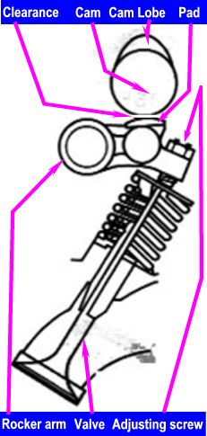 |
Valve clearance is the distance or
gap between the cam and the top of the valve. Because the NSX has a
rocker arm between the cam and valve, we measure this clearance as the
distance between the cam and the rocker arm pad (where the cam lobe
actuates the rocker arm). We adjust the clearance by turning a
set-screw located at the end of the rocker arm. The bottom of this
screw effectively rests on top of the valve, so turning the screw
clockwise moves the rocker arm up towards the cam (less clearance),
and falls away (more clearance) if we turn the screw counterclockwise.
We need to occasionally check and adjust valve clearance because the these
components wear slightly with use and the clearance may fall out of the
specified range resulting in extra wear (not enough clearance) or lost
performance and noisy engine (too much clearance). Its been our
collective experience that the NSX's valve clearance stays well within its
service limits between service intervals. Honda raised the service
interval for the 1996 cars to every 30k miles and 1997+ models are
adjusted at 30k and then every 60k miles thereafter.
we can do some damage to our engines if we set our clearances too tight,
along with extra wear we can make it so the valves don't seat properly,
which can result in damaged valves, which is not good$$$.
Fortunately, with a little time and attention to detail, this is easy to
avoid. Our goal is to keep the clearance within the service manual
specifications and try to be consistent with our adjustments and measurements.
The first few clearances we check and adjust can be a
little frustrating and take a bit of time, but we'll soon get the hang of
it and it really becomes quite easy. After I've finished all 24
measurements/adjustments,
I usually go back and quickly re-check them again, just to make sure
everything's OK.
Please read more about valve
clearance from www.nsxprime.com
The NSX FAQ.
|
Tools & Supplies
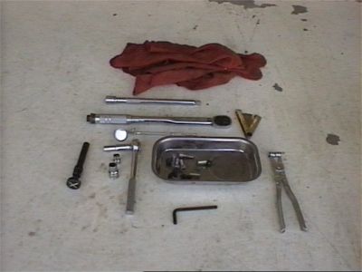
Prepare Tools: We'll need a 10mm deep-well and regular socket,
12mm socket for OEM strut bar or 9mm hex wrench for most aftermarket strut bars,
a 19mm socket (same as your lug nut socket) with a long extension (at least 16")
and a 17mm combination wrench (not pictured). Well also need feeler
gauges (.006 and .007 inches). A micro torque wrench is helpful if
you're not used to tightening screws to low torque values.
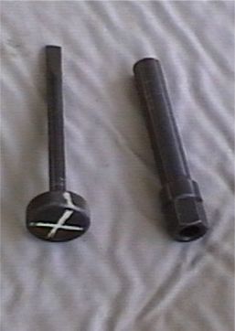
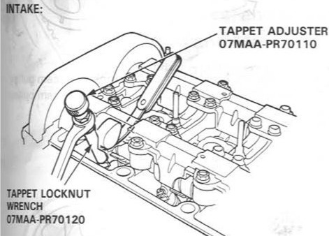
Prepare special tools: 07MAA-PR70120 tappet locknut wrench and 07MAA-PR70110
tappet adjuster. These special tools allow easy adjustment of the valve
clearance. Tip: draw an "X" on the top and sides of the tappet adjuster with a
paint marker. This visual reference is a real time saver.
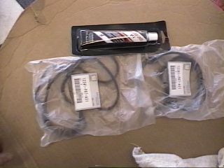
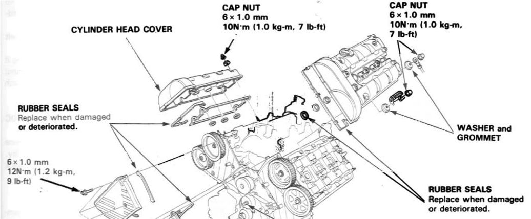
Prepare special parts: It's a good idea to have some head
cover seals and some Honda bond to replace any seal that's damaged or
deteriorated. I've replaced mine only once and have had my covers off
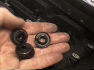
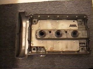
several times so you may not need to replace your seals. Each cover has two seals, one small one, which seals the timing belt bay, and a
large one, which seals the rest of the cover. There are also three round
doughnut-type seals, which seal the ignition holes. I have never replaced
mine, however I'll probably replace them just for fun next time I have the covers
off.
Prepare car and mechanic: The service mat is a
worthwhile investment for this procedure--plus it looks cool. Make sure
you allow yourself enough time and energy to do a good job with this
procedure. If you find yourself in a time crunch or are getting frustrated
you can always close the engine hatch and come back to the project later.
You may want to find a short stool or something similar to stand on to help reach the
exhaust cams. I stand on the spare tire with a non-skid carpet underneath.
Note: we have to perform this procedure with a cool engine (under
100F). Remove your belt or any jewelry that will scratch the paint as you
lean up against the car.
Remove valve covers
Step 1: Jack up car as low as
possible and remove right rear tire.
Step 2: Remove coil
covers and coils (Steps 2 - 5b)
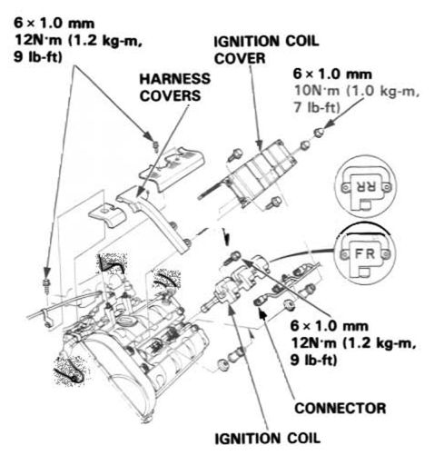
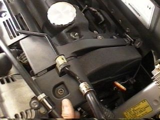
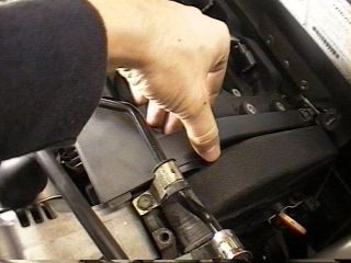
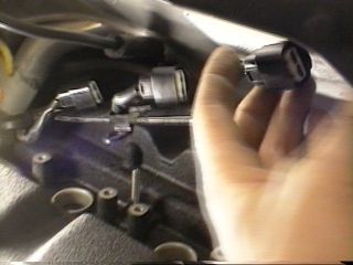
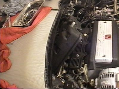
Step 3a: (Remove front cover) remove the PCV valve, driver's
side wiring harness, passenger's side harness covers,
and brass spacers (see pictures above and below)
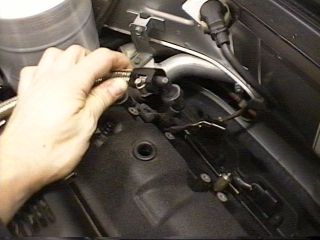
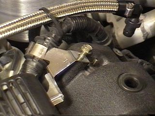
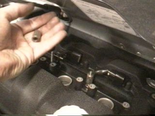
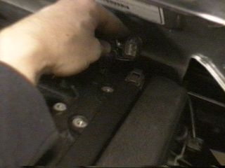
Step 3b: disconnect the front oxygen sensor (press on tab and
pull apart) and clear the ignition connectors out of the way
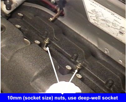
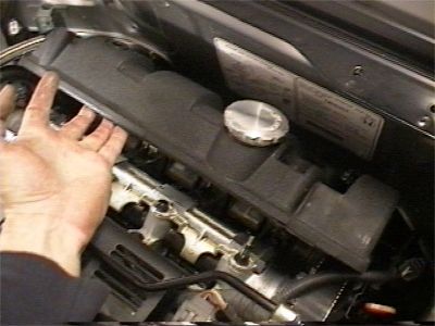
Step 3c. Remove front valve cover: We'll use our 10mm deep-well
socket to remove the two 2 nuts located at the bottom of the threaded rods
sticking out of the cover (see picture above). Using the same wrench, we
can remove the 4 black acorn nuts on each corner of the cover. Once the nuts are removed, try to
raise the cover a few centimeters, this will break the gasket seal and break
free the six rubber grommet washers. These six washers are a real pain, I
like to collect all six of them before removing the cover as they have a tendency
to get lost; there are 4 of these washers: 1 under each acorn nut
you removed and two in the center around the 2 threaded rods.
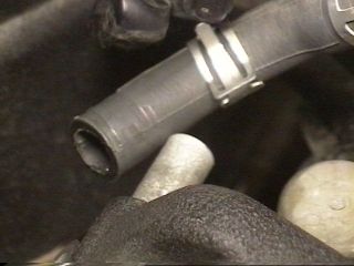
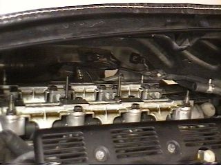
Step 4: (Remove rear cover) Remove rear oxygen sensor connector,
rear cover breather hose (use pliers on spring clamp), 4 acorn nuts, 2 center
nuts and grommet washers. Lift head up slightly and carefully rotate 90
degrees rotating the passenger
side of the cover to the rear. Be careful not to damage the timing belt or
rubber cover seal, then carefully pull cover out.
Measuring and Adjusting
Valve Clearance
We measure valve clearance by measuring the gap or free play
between the cam and the corresponding rocker arm. To measure this gap, we
need to make sure the valves for the cylinder we are measuring are in the closed
position.
We do this by positioning the appropriate piston at TDC (top dead center) of the
compression stroke, which insures that both intake and exhaust valves are fully
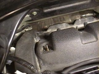
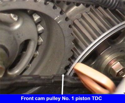
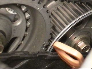
closed and the cam lobes are not engaging the rocker arms. Fortunately. it's easy for us to position our valves in this manner. The numbers 1 through 6 are stamped on the outside of the intake cam
pulley on the front cylinder bank. When the number on the cam pulley is lined up with
the timing belt cover (see picture below right) then that piston is at TDC.
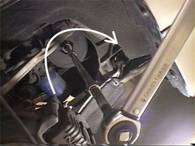
Positioning the cam for measurement/adjustment
To position a piston/cam at TDC, make sure the transmission
in neutral and use the 19mm socket and long extension to rotate the
crankshaft pulley clockwise until the desired cylinder number stamped on
the cam pulley is lined up with the timing cover. The crankshaft should
turn with moderate force, so if you find yourself really leaning on the
wrench then double-check to make sure the transmission is in
neutral. Rotating the shaft counterclockwise is not a good thing as it may
skip a tooth on the timing belt, which is bad. The picture below shows
that cylinder #6 is at TDC and the valves are ready to be measured/adjusted.
 |
We will be measuring/adjusting the
clearance on each of the four valves per cylinder--two intake valves and two exhaust
valves. The intake valves tend to be easier to measure/adjust because they
are relatively accessible--located towards the center of the engine where
the intake plenum runs. The exhaust valves are a bit challenging, especially
at first, but they get easier. Tip: it may be easier to start with cylinder #4 as it is the
most assessable.
|
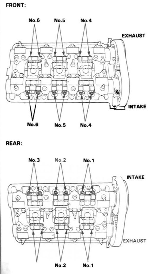
Measuring intake valve clearance (looking from driver's side at the rear cylinder
bank)
Measuring exhaust valve clearance (looking from driver's side at the rear cylinder
bank)
To measure valve clearance we need to insert the feeler gauge
between the rocker arm pad and the cam we are measuring. Study the two
Service Manual diagrams above and notice how we measure from the center of the
cylinder bank out. The tip of the gauge should poke out from under the cam
and point at the adjusting screw--we can see this when we adjust the intake
valves. Sometimes the feeler gauge has a tendency to migrate towards the
mid rocker arm so double-check the position of the gauge to make sure it's under
the proper rocker arm. Tip: to make measuring easier I remove all but the
.006 and .007in gauges from my set.
...better pictures coming soon (as soon as I can get this damn
cast off my right hand <g>)
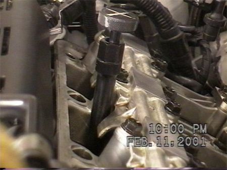
One of the most frustrating tasks involved with this procedure is
figuring out how to properly position the tappet wrenches by feel on the exhaust
side. I always find that the locknut tool needs to be angled more
horizontally than I expect to fit on the exhaust locknuts.
Adjusting order
There are several ways to go about this procedure: we can start by adjusting
just the intake valves on all the cylinders, or do one cylinder bank at a time
or move from bank to bank in sequence with the numbers on the cam pulley--as
long as we hit all 24 valves, order really doesn't matter. If it's your
first time then it might be easier to start with cylinder #4 and work down the
front cylinder bank #4, #5 and #6, which gives you time to get the hang of it
before tackling the rear bank, which is less accessible.
Now let's take a detailed look at measuring and adjusting the
clearance for a valve:
Measuring
We'll start with an easy one, cylinder #4, which is located on the front
bank passenger's side. Turn the crankshaft so that #4 is at TDC
position. Let's use our .006 inch feeler gauge to measure the clearance on
the intake valve closest to us. Slide the gauge between the cam and rocker
arm until you can see the point of the gauge coming through the other side and
pointing at the adjusting screw. You'll probably have to monkey around
with the gauge a little bit to find the right angle that allows the gauge to
slide in there.
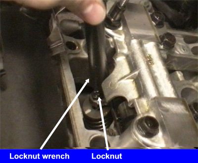
Loosen the locknut
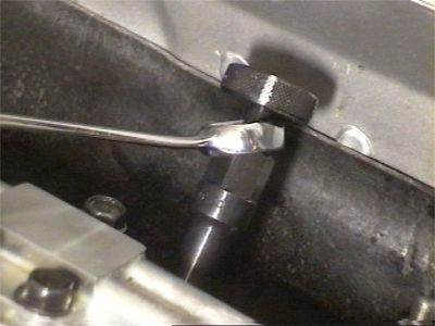
Now, place the locknut wrench over the adjusting screw locknut on the rocker
arm and slide the adjusting wrench down inside the locknut wrench and turn the
head (of the adjusting wrench) until the blade of the wrench engages the
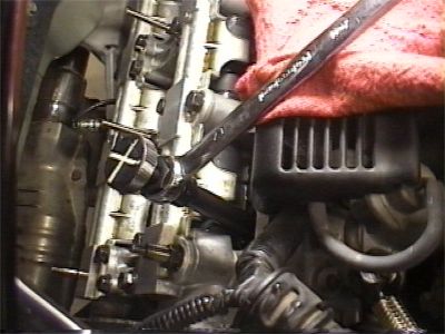
adjusting screw. Now we're ready to loosen the locknut by placing the open
end of the 17mm combination wrench on the locknut wrench and turning it
counterclockwise about a 1/4 turn. In the pictures above you can see that
I use the closed end of the wrench, but using the open end is probably easier at
first, especially for the exhaust valves.
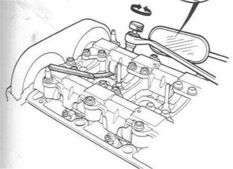
Adjust
Now that the locknut is loose and the feeler gauge is in between the cam and
rocker arm, we can play around with the clearance. If we turn the head of
the adjusting wrench clockwise (it will turn quite easily by hand) it will
reduce the clearance, counterclockwise will increase clearance. As we turn
the wrench, we can move the feeler gauge back-and-forth to feel the changing
resistance. Specified clearances for the intake valves are .006 - .007 and
.007 - .008 for the exhaust valves. Turning the adjusting wrench just a
few degrees will move the clearance in/out of these specified ranges. To
set the intake clearance, use the .006 (.007 for exhaust) gauge and turn the
adjusting screw so that there is a bit of resistance or drag on the gauge when
you move it back-and-forth. If you're not familiar with using feeler
gauges then it's good practice to double-check your work by using several
blades. Try the .007 gauge, if it fits that's OK, but it should be
tight. However, the .008 (.009 exhaust) should not fit. The .005
(.006 exhaust) should fit quite easily and have no resistance. We'll get
quite proficient at this after doing 24 of these babies and probably be able to
set the clearances perfectly using only the.006 (intake) and .007 (exhaust)
gauges.
Tighten the locknut
Once the clearance is set, then we need to tighten the locknut. Place
the open end of our 17mm combo wrench and tighten (14 lb-ft. clockwise).
Keep an eye on the adjusting wrench head to see if it moves when you tighten the
locknut, if it does, then most likely you'll have to re-adjust the clearance and
re-tighten--you may also be over-tightening the locknut. After tightening,
always re-measure the clearance and re-adjust if necessary.
Repeat
Repeat the above: position, measure, loosen, adjust and tighten for each of
the 24 valves. Take your time and have fun with it.
Re-check
When you've finished measuring/adjusting all the valves, it's a good idea to
go back and quickly re-check all the clearances. This is a good way to
catch any mistakes or variations in measuring/adjusting consistency. Now
that we're so good at it, it only takes a few minutes.
Valve Clearance Summary
Start with cold engine
Jack up car and remove right rear wheel, strut bar, 12mm socket or 9mm hex
Remove coil covers and coils 10mm socket
Remove wiring harnesses that connect to head covers, PCV valve, breather hose,
O2 sensor connectors
Remove 4 black acorn nuts, 2 center nuts and rubber 6 grommet washers, 10mm
socket, deep-well 10mm
Remove head covers, rear cover rotate passenger's side 90 degrees back and then
pull out
Move desired piston to TDC and set clearances .006 - .007 inches for intake,
.007 - .008 for exhaust, 14 lb-ft. locknut torque
Re-check all when finished
Installation
Installation is basically the reverse of removal. Check
the seals on your head covers to make sure they're not deteriorated or damaged.
If they are then spot-dab a little Honda bond between the head cover seal
channel and the new seal to help keep it in place during installation. Before I
install the covers, I like to give the heads a once-over with an inspection
mirror to check for anything that may have fallen in there during the
procedure. After you have installed the covers, but before you have
started to tighten them down, spend some time with an inspection mirror and
follow the head seal around the cover. Look for a good seal and watch out
for wires that may be caught in there, like that nasty rear oxygen sensor wire,
which likes to get in there and mess up an otherwise perfectly good seal.
Torque values:
Head cover acorn nuts and center nuts - 7 lb-ft.
Over-torque these babies by too much and you'll snap a stud.
Ignition coils - 9 lb-ft.
I like to re-torque the head cover nuts after I've installed
the ignition coils
Make sure you've got all everything put back together, like the
front and rear O2 sensor connectors and the grounding cable on the front
driver's side acorn nut.
Once everything is back on, run the engine for about 5 minutes
and check for oil leaks around the cover seals.
Way to go! That was so easy let's do it again! ...OK, maybe next
year.